We use cookies to make your experience better. To comply with the new e-Privacy directive, we need to ask for your consent to set the cookies. Learn more.
Arched Mirror Routing Project
An elegant arched mirror frame constructed using a series of short wood lengths and butterfly insert joints.

This Arched Mirror frame has been constructed using a series of short wood lengths, with each joint featuring two timber butterfly inserts that have been dovetailed into the end of each section. As well as being decorative, the butterfly inserts are functional and can significantly increase the strength of a butt joint.
Made from Walnut the butterfly inserts stood out well against the oak, with an eye-catching contrast of the two timbers, enhanced when oiled during the finishing stages. Various other combinations of contrasting timber would work well for this project as an alternative to oak and walnut, or this combination could be reversed. This project includes how to make these butterfly joints using a router.
After working out the size of the frame, its thickness needed to be calculated. The thickness of the lipped inner front edge, the mirror, backboard and fixing area to secure them needed to be considered, so that a deep enough rebate could be made in the back of the frame.
Step 1 - Make templates
A template for making the arched sections should be made, this example uses some 6mm MDF sheet material. The template will enable you to copy and repeat the arched segment pattern into the work-piece material, with the assistance of a bearing guided cutter.
To make the template, the inner and outer diameters of the arch should be marked out onto the template material. The semi-circle then should be divided into 3 equal segments through the centre point. The number of segments could be varied, depending on the size of the frame you wish to produce.
Using a Router attached to a Router Compass (pictured Trend Ref. T5EK & R/COMPASS/A) set the jig's radius to that of the frame's outer profile and rout an arc with a 4mm diameter TCT cutter. Using a small diameter router bit will help to keep the MDF dust to a minimum.

Then reduce the radius of the Router Compass to the frame's inner profile, and rout another arc. Cut out the section, cutting the ends slightly longer than the segment lines so that a bearing guided cutter can have a smooth run up when trimming the work-piece.

A template of the frame's inner curve can also be made to assist in maintaining the correct shape during the gluing/cramping stages. To make the template, increase the radius of the router compass from the previous setting by the diameter of the cutter being used. You may need to re-position the pivot point to allow clearance from the previous cut made, and rout a semi-circle. This can then be cut down the centre line to produce an exact semi-circle.
Step 2 - Prepare Timber
Next we will take a look at preparing the timber to be used on this project, we will start by planing and squaring up our timber before moving on to forming it to the required shapes.

Material for the frame can be planed to the required thickness. Care should be taken to feed the timber into the planer machine with the grain running the correct way to prevent the surface from tearing out. If using off-cuts of timber, ensure that the pieces are long enough to pass though the thickness planer safely.

Timber for the straight sections should be ripped down and trimmed to match the width of the arched template. This could be done in a thickness planer if available or on a router table fitted with a straight TCT cutter.

The straight sections of timber need to be cut to length. A chop saw fitted with a negative hook blade is ideal for this. A spelch block should be fitted to the saw's back-fence to prevent grain tear-out at the back of the work-piece. It is vital that the straight section ends are cut squarely to ensure that the frame assembles correctly.
To cut parallel strips on a router table, use a clamp guide fitted to the table surface on the left hand side of the cutter. Ensuring the timber has a flat edge on the bar to prevent rocking, the clamp guide can be locked into position to take a light cut. The timber should be held firmly into the bar as it was pushed through, keeping fingers a safe distance away from the cutter.
Once all the timber sections have been trimmed on one side, the clamp bar position needs to be moved in slightly so the other sides can be trimmed, creating parallel strips of timber.
Once all the timber sections have been trimmed on one side, the clamp bar position needs to be moved in slightly so the other sides can be trimmed, creating parallel strips of timber.

Next, lay the curved template over one of the blank timber pieces for the curved section. The template's segment lines at the inner curve points should be positioned in line with the material edge. This will allow you to mark the angles required on the ends of the curved sections the same, which is 60 degrees. (Based on three segments in a semi-circle). These lines should be repeated on the other curved sections.

With the angles marked, the section ends should be cut on the chop saw at this stage, before cutting the curved areas, so that the back of the timber can be supported on the saw's back fence.

The template should then fixed in place to an arched section using double-sided tape, lining up the segment marks on the template with the ends.
For best adhesion, the surfaces should be wiped clean and pressed lightly with a cramp to avoid the template from slipping during routing. The shape should be cut, leaving a slight overhang for trimming with a router.
Step 3 - Machining the Arched Section
The curved sections can then be trimmed flush with the template using a bearing guided cutter. This stage will be much easier to machine using a router table.
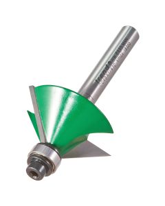
To avoid the grain from tearing out of the curved edges during trimming, a cutter with bearings fitted on the nose and shank of the cutter should be used (Trend Ref. 46/300X1/2TC). This will allow the template to be followed underneath or on top of the work-piece accordingly by adjusting the height, therefore all of the curve could be routed with the grain.

The inner edge of the curved work-piece should be trimmed using the top-mounted bearing (table set-up) from the start to the middle of the approximate centre point of the work-piece. Then the outer profile of the same end can be routed.

The work-piece should then be turned upside down so that the template faced onto the table surface. The router height can then be raised so that the bearing mounted on the shank could be guided against the template from underneath the work-piece. This will allow the other end of the curved section to also be trimmed with the grain.
This process should be repeated for each curved section.

The curved sections can now be laid around the edge of the semi-circle template so that the ends could be checked for good joins. Although the joints should be reasonably accurate if the procedure in step 2 has been followed, the ends could be finely adjusted if required by fine sanding with a flat sanding block, or with a bench-mounted disc sander.
All the frame sections should be laid out together and joints edge marked and numbered.
Step 4 - Dovetailiing the Joint Ends
It was then time to cut the dovetail slots into the ends of the work-piece sections. Although these dovetails could be cut out using the traditional method of hand-tools, using a suitable dovetail router cutter and jig will save much time, whilst producing accurate results. Alternatively a dovetail cutter in a router table could be used if the work-piece could be vertically supported sufficiently.
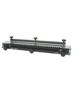
Here we recommend using the Trend DC400 dovetail centre, which has a variable layout facility, allowing the tail and pin guide fingers to be adjusted in 2.5mm increments. This jig also has two guide rails, therefore the router is supported on both sides of its base and prevents the router from tipping. It is a good idea to make trial cuts before machining the work-piece to check layout is visually pleasing.

The tail guides should be laid out on the DC400 so that two dovetails would be symmetrically positioned on the material width. Refer to dovetail jig instructions for full set-up details.
To prolong its life and put less strain on the dovetail cutter, you can make relief cuts with a straight cutter first, removing the majority of the waste material. Therefore the dovetail cutter would only have a light cut to make and the waste material would have more room to clear, achieving a better finish.

With the guide bush remaining in place, the 14 degree TCT dovetail cutter was fitted to the router.
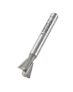
There are several Trend dovetail cutters that have a 14 degree angle and are therefore suitable to match the butterfly spline bit for the butterfly inserts, here we use the Trend Ref. L120X1/4TC, which has a 12.7mm cut length.
If using a dovetail jig for this operation rather than a router table, the maximum shank size that will fit through the guide bush of the jig needs to be considered.

The joint at the bottom corners of the frame comprises of a side grain to end-grain joint, therefore these side sections needed to be fitted horizontally in the jig.
Clamping a piece of waste timber behind the work-piece timber being routed prevented the back from break-out. Therefore the frame's front surfaces were faced inwards towards the jig body. Slots should be routed in all the required dovetail positions.
The depth was set to slightly less than the dovetail's cut length.
The front bar of the jig is designed to accept the material vertically, however if the timber is inserted horizontally in the front bar as needed with this corner joint, the material needs to be a minimum width of 75mm for the clamp mechanism to work correctly and a maximum length of 400mm. Maximum clamping thickness 25mm.
Step 5 - Making the Butterfly Inserts
A Butterfly Spline router bit should be used to make the butterfly profiles. (Trend product Ref. 10/40X1/2TC) This cutter needs to be used in a router table with a 1/2inch shank capacity router for accurate results.

It is prefferable to use a reasonably wide piece of timber so that a strip of the butterfly insert profile could be made and cut down into a number of pieces afterwards, saving machining time.
The insert material should be machined to the thickness of the dovetail slots width (12.7mm if using the L120X1/4TC cutter), although if it is slightly thicker than required it could be adjusted later. Ends neeb to be trimmed square.

A false fence can be clamped to the back fence to bridge the left and right fence cheeks. The height of the cutter can then be adjusted so that the outer point of the cutter is equal to the depth of dovetails that have been cut in the frame sections. A fine height adjuster is useful for this.
Making sure the power is disconnected, the cutter should be rotated until the blade was positioned at its maximum cutting point to the timber. This will enable you to set the table's back-fence, by lining the bottom corner of the timber with the cutter. If the fence is moved more forward than this and timber cut, the width of the butterfly will be reduced.

With the fence locked in position, the timber can be pushed through vertically. It is advisable to make a trial cut at this point to check the cutter is aligned with the timber correctly. A side finger pressure was fitted to the table to help hold the timber to the fence.
The timber should then be rotated 180 degrees and the second side routed. If the insert material being used is thicker than required, the back-fence can be moved over to allow the cutter to trim down the thickness.

The routed section can then be cut down as a strip to the overall length of the butterfly. A table saw fitted with a fine finish alternate bevel tooth blade is ideal for this.
The timber was pushed through with the strip on the off-cut side of the blade, therefore fingers are kept away from blade. Alternatively a hand held tenon saw could be used.

The butterfly strips can now be cut into pieces, slightly over the thickness of the frame so that they could be finished flush when glued in place.
A chop-saw with a fine tooth blade is ideal for this. A false fence should be fitted to the back-fence and saw bed to prevent the grain from breaking out. A side stop can also be fitted so that all the butterfly inserts are cut to the same thickness.
Step 6 - Assembling the Frame
To begin each insert should be checked for fit in its position. Rather than try to glue several joints at once, we recommend gluing just one or two joints at a time. This will allow you to apply end pressure to each joint as it was being glued, helping produce a strong joint.

To maintain a flat frame the components should be clamped to the workbench to prevent distortion.
Put some plastic underneath the joint to prevent any oozing glue from sticking to the bench surface.

The joints should be clamped end-to-end and downward pressure applied. Padded bar clamps are ideal for this since they do not mark the work-piece (Trend Ref. BCS/6).

Using the semi-circle template made earlier to hold the correct shape, the first curved section can be clamped.
Blocks can be made to protect the corners of the curved section from crushing whilst being clamped end to end.
Since clamping a curve causes the middle to give way, the middle should be pushed into the template by the use of a spreader (The Trend Bar Clamp can be re-arranged to act as a spreader).
Once the first curved joint was dry, the process was repeated adding the next curve section. When all the joints were glued and assembled, the butterflies were planed flush with the frame.
Step 7 - Rebating the Frame & Routing Keyhole Slots
The frame should be clamped faced down on a clean, flat work surface, ensuring there are no particles that could scratch or damage the frame.

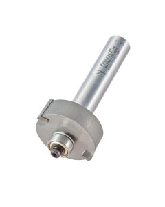
Using a rebate cutter (Trend Ref. 46/39LX1/2TC or C040X1/2TC) and attaching a small piece of material of the same thickness as the frame to the router base (known as a shoe, this prevents the router from tipping), the rebate can be routed in several passes to reach the required depth.

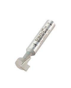
Next, keyhole slots can be routed into the back of the frame so that it could be fixed flush on the wall (Trend Ref. 35/0X1/4TC).
Begin by routing relief cuts using a straight cutter that is slightly smaller in diameter than the neck of the keyhole cutter to remove the bulk of the material.

The keyhole slots were routed, plunging down at the lower end of the slot and applying the router's locking lever to ensure the cutter remained at the required depth.
Remember not to release the plunge lock until the router is clear from the slot or the result will be a double ended keyhole- which will not secure the fixing!
Step 8 - Making a Backboard & Finishing
At this stage the frame is ready to be sanded,

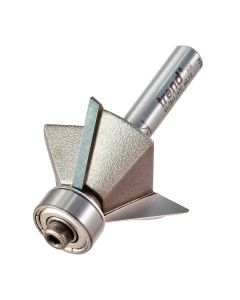
A small chamfer can be routed on the frame edges to remove the sharp corners, using a bearing guided 45 degree cutter with 3 flutes for a fine finish (Trend Ref. 41/5X1/4TC or C049X1/4TC).

Cut a backboard from 6mm MDF to sit behind the mirror. Start with a rectangle slightly under the size of the overall length and width of the rebated area then use the router compass to rout the arched top.

Finally a finish should be applied to the bare frame. After leaving the oil to penetrate for a few hours, another coat should be applied and any residue wiped clean with a cloth.

The completed frame with mirror fitted.
Related Products


Related Videos
Bearing Guided Cutters
CDJ300 Dovetail Jig
CDJ300 Dovetail Jig
Related Downloads
Related Test Reviews
Related Instructions

Document Download
Document Download
Document Download
Document Download
Document Download
Document Download
Related Files
Document Download
Document Download
Document Download
Document Download
Document Download