We use cookies to make your experience better. To comply with the new e-Privacy directive, we need to ask for your consent to set the cookies. Learn more.
Photo Clock Routing Project
A fun versatile clock where you can exchange the photographs on the clock face in a matter of minutes.

We all have clocks and family photographs lining our mantle pieces but how many have a Photo Clock combination? No problem if you have a router and the time to follow my instructions!.
One attractive point is that you can exchange the photographs on the clock face in a matter of minutes.
Having obtained a seasoned panel of timber, minimum 400mm wide and thickness 25-28mm thick, the project involves producing the clock by machining with a router a circular shaped workpiece, the rear part being recessed to accept a small electric clock motor with hands, locking flange and nut (see photograph in Step Ten).
Measurements: Outer diameter of the finished clock =330mm.
Shallow circular recessed area on front face =220mm diameter, with cutting depth being 2mm.
Recess diameter to accept clock motor at back =100mm, with cutting depth being 16mm.
Shallow circular recessed area on front face =220mm diameter, with cutting depth being 2mm.
Recess diameter to accept clock motor at back =100mm, with cutting depth being 16mm.
Step 1 - Preparation of the Clock
This stage involves creating the shape of the photo clock.

With a large self-made compass, scribe two circles on the surface of the workpiece = the face of the clock.

Circle A), the outer one, draw 330mm diameter.
Circle B), the inner one, draw 220mm diameter.

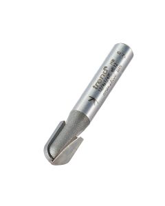
The first machining operation is to cut a decorative radiused groove about 20mm within the perimeter line scribed in Step One (Circle A). This is done with Trend's T5 router fitted with a beam trammel. The radius cutter, Trend Ref. 12/4, is 8mm in diameter. A shallow 3mm radiused groove will give an attractive finish to the final product.
Step 2 - Routing Application
Now, the clock hasto be routed.

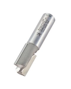
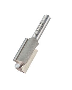
Surfacing the inner (220mm) face area of the clock is done in two stages. The first stage involves cutting a 16mm wide swathe within and around the marked edge of scribed area, again using a beam trammel. The recessing is done with a 16mm diameter two flute cutter (Trend Ref. 4/2). The second stage described in Step Four involves machining freehand the area within the cut swathe.

To machine 2mm deep the surface within the cut swathe described in Step Three, first remove the beam trammel. Then mount on the router base an 'anti-tip plate' made for good vision in clear acrylic sheet, 6-8mm thick, fixing it in place using double-sided tape.
Size ideally should be 300mm square. This avoids the router tipping during the routing process. A central hole at least 20mm in diameter is drilled in the plate to give clearance for the 16mm cutter. The router must now be set for 2mm cutting depth below the plate and locked. The whole surface within circle B can now be machined freehand, (220mm dia. by 2mm deep).

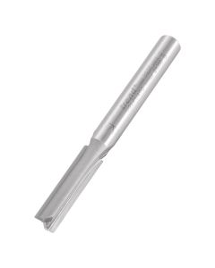
The main clock area, 330mm diam. by 28mm deep, now needs to be cut and removed from the wood panel. For this purpose, both router and trammel is used as previously. But a 1/4Ó diameter TCT cutter with a minimum 25mm long flute is needed for cutting through the 28mm material. (Cutter Ref. 3/22). A series of five or six passes is needed to cut right through the material, depth of cut being increased by 5-6mm on each rotation.
Step 3 - Adding Front Features
This stage involves forming the photo clock design.

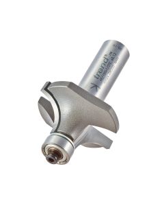
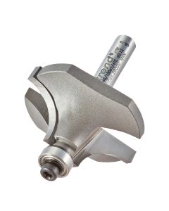
To machine a radiused profile on the top edge of the clock, a router table is the best option. Trend's PRT Router Table was chosen to accept the T5 router. A self-guiding rounding over cutter, Ref. 46/150, is fitted to the router which cuts a 12.7mm (1/2") radiused profile on the top edge of the clock. In operation, the workpiece is rotated anti-clockwise face down on the table with the bearing part engaging the vertical edge of the workpiece.

Twelve mushroom shaped pellets to indicate the 12 hours of the day are to be inserted around the clock edge. To set their exact positions, a paper pattern with 12 arms is placed over the clock face to denote the points where the pellets will be recessed. A gimlet is shown piercing the 12 points prior to drilling the holes to receive the pellets shown in Step 8.

The button pellets which can be bought in, or self-made from dowelling, can be in various diameters. For this project, the pellet tops were 12mm diameter, with their 3mm projecting shafts being 8mm diameter.
The photograph shows holes being drilled 3mm deep to receive the pellets.
Step 4 - Creating functionality

To receive the clock motor, a 16mm deep recess needs to be cut in the back of the clock. A template is needed and Trend's acrylic template was selected, Ref. TEMP/COR/A. This has an aperture of 100mm diameter which gives clearance to receive the clock motor. The T5 Router was again used but fitted with a 20mm dia. guide bush, (Trend Ref. GB20) and a 16mm diameter cutter with 25mm cutting depth, (Trend Ref. 4/26).
The router is applied in stages, increasing the cutting depth gradually, but ensuring that no less than 6mm wall thickness remains for securing the clock motor in place with the flange (see Step Ten).

Underside view of recess on clock and close-up of cutter and guide bush.
The template must be mounted exactly central over the hole which is to accept the clock spindle.
It can be screwed or held in place by double-sided tape.
It can be screwed or held in place by double-sided tape.

The assembly of the clock motor, size approx. 60mm x 60mm x 15mm deep, can now proceed. This is inserted into the recess in the back of the clock with the pin passing through for locking with a brass flange at the front of the clock. This flange is easily removed to accept photographs etc., which require an 8mm hole to be cut centrally. They need to be cut 220mm diameter to nest in the 2mm recessed area and held in place with the threaded flange.
A. Brass Flange. This screws into the motor recessed within the back of clock.
B. Flange secures the motor in place, a 10mm diameter hole is needed to accept flange.
C. Photo needs centre drilling 10mm diameter for holding in place by the flange.
D. Motor pin passes through the centre of the flange, with hour hand sliding onto the pin shaft. The minute hand is held in place by a knurled nut.
For health and safety reasons, dust extraction devices should always be used in confined spaces.
In this feature, for reasons of clarity within illustrations, dust hoods, ports etc., have been excluded.
In this feature, for reasons of clarity within illustrations, dust hoods, ports etc., have been excluded.

The completed Photo Clock Routing Project.