We use cookies to make your experience better. To comply with the new e-Privacy directive, we need to ask for your consent to set the cookies. Learn more.
Top Table Routing Project
This is a quick low cost project in MDF using a template system. Great for making batches of furniture for selling.

This is a really quick little project to make and involves very little cost in the way of materials, or you need is a few bits of MDF. However, there is quite a lot of routing involved using templates, but this is not difficult and is a superb way to get consistently sized components making it an quick and easy mass production technique if you´re thinking of making batches of furniture for sale.
Although MDF is a superb material to work, remember that any machining operation produces vast amounts of very fine and unpleasant dust, so always take suitable precautions. I wear a respirator mask during the basic cutting operations and an air fed helmet for the routing work, as this is a particularly dusty process.
This particular table was designed for a small bathroom, hence the use of the tiles, but you could easily modify its with the play piece of MDF or even a solid wood top.
Step 1 - Select and Prepare Timber
Start by making the leg template and use this to mark out the eight components required for the four legs. In reality four of these need to be narrower than the others by an amount equal to the thickness of the material being used, but as I was only making one table it seemed unnecessary to make two separate templates. So I cut all the leg components to the same size initially and then reduced the width later.
However, If you are gearing up for mass production, even small amounts of waste like this soon accumulate into significant amounts, so it is more viable to make proper sized templates for each component

Start by making the leg template and use this to mark out the eight components required for the four legs.

I used a bandsaw to cut the legs out, as the quality of the cut is irrelevant at this stage. In fact you need to cut them all about 2mm oversize.

The bandsaw is the ideal tool for this job. Don´t make them too much bigger, or the router will have to work that much harder to trim them to size later and you will also generate unnecessary amounts of dust.

Stick the template onto the leg blank using a couple of pieces with double-sided tape, making sure it is centred to leave an even amount of overhang all way round.

For the trimming operation you´ll need a bearing guided cutter and for this particular job I find the cutter with a bearing on the bottom is easier to use than one with the bearing on the top. This latter type are better suited for use in a router table.

With the leg and template combination clamped firmly to the bench, you can then run round the outline to produce a perfect replica of the template.
Step 2 - Making the Legs
The next stage involves the construction of the table legs, ensure all legs are equal in length and width in order to produce a stable table.

Keep repeating the procedure for all the blanks and then cut a strip off four of them equal to the thickness of the material being used.

This makes the two sides of the leg an even size when there are glued together later.

The simplest way of joining the two halves of each leg at right angles is to use biscuits and once again you can use the router for this with a suitable slotting cutter fitted with a bearing. Trend Ref. 342.

The narrower leg components are easily slotted as they can be clamped face down on the bench and still give plenty of support to the router.

For the other half which has to be slotted on the face, increase the support for the router by clamping it to a wider piece of spare material in the vice. This ensures that you keep the router upright. Provided you don´t change the setting of the router for the two components they should fit together perfectly, no matter where the slot is centred.
Notice that I have not actually formed the slot in the centre of the leg thickness but move it well towards the inside to minimize the chance of exposing it later with the rounding over cut on the corner.

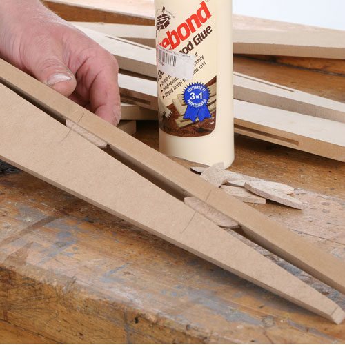
Glue the two components together and use plenty of clamps to pull the joints up really tight, getting plenty of glue into the biscuit slots to make them swell and grip properly.

Once they have set, the legs can be sanded gently to make sure the joint is perfectly flush, but don´t overdo this sanding or the surface will be much harder to finish later. Sanded surfaces always seem to rough up more after painting than the original smooth MDF surface.

Now you can apply the rounding over cutter down the corner of each leg, a simple job using a bearing guided bit. Trend Ref. 46/130X1/4TC. Be careful that the router does not tip when you are working on the very narrow lower section of the leg.

To finish off each leg, glue in a triangular support block at the top. As well as strengthening the leg, this also gives you a means of fixing it to the top, so make sure it finishes perfectly flush with the ends of the uprights or it won´t end up square to the top.
Step 3 - Construction of the Table Top
For the top, I decided to set in some ceramic tiles to match those already being used in the bathroom, and there are various options for doing this. I could have used a single piece of solid MDF and routed out a hole for each of the tiles. Another alternative is to use the piece of thin material as a baseboard and then stick on strips around each tile to make up the required thickness. In the end I opted for combination of both of these techniques and use two pieces of thin MDF, one as a baseboard and one with holes routered in it for the tiles.
To achieve this you will need another template, a guide bush and a suitable straight cutter. The first stage is to make a template of the correct size to form the tile recess. You can either make an internal or an external template, but in this situation I find it much easier to make and use an external template. However you cannot just make it the same size as the tile or the recess with far too big, you have to make allowance for the guide bush margin and the diameter of the cutter itself.
The guide bush margin is determined by the following calculation:
Deduct the cutter diameter from the outside diameter of the guide bush and divide by two.
For an external template you need to add on to this the diameter of the cutter, to give the amount that has to be subtracted from each template dimension. In this case each side had to be 11 mm smaller than the finished tile dimension.

Identify your material of choice for the top boards and cut to prefered thickness (I used 2 sizes of MDF).

I used an actual tile to get the initial size for the template, and then reduced each dimension by 11 mm. As the tiles are going to be grouted in, it is better to leave the recess slightly oversize to ensure they will fit, so make the template a fraction oversize.

The position for each tile is marked out and the template stuck in place with double sided tape. Also stick the workpiece to a sacrificial work-board so that when you plunge through and make the cut, the central offcut that you release remains secure and cannot move about into the spinning cutter.
Use steps below to create an effective template.

To prevent the router tipping during the template cuts, is a great help to temporarily stick a scrap of the template material to the router base, as the slightest wobble will be reproduced in the edge of the tile recess.

For an external template like this, work anti-clockwise to prevent the router wandering away from the template, and make the cut in a series of shallow steps to avoid overloading the router or vibrating the cutter.

Also, if you take light cuts it is much easier to keep the guide bush in contact with a template. If you have to start forcing a deep cuts you never sure that is contact his being maintained. If you are working with an internal template feed the router clockwise.

Once you´ve cut all round the template the centre can be removed by gently levering it off the double sided tape using a flat chisel.

Make sure the cutter only penetrates about 1mm into the work-board beneath as this is enough to leave a clean cut and should minimize the dust problem.

Repeat the procedure for all the other recesses by resticking the template in position each time.

The corners of the recess are obviously rounded.

These are quickly squared out using a fine saw or chisel.

I also very slightly radiused the top edge of each recess using some fine abrasive paper.
Step 4 - Final Assembly
Now, its time to construct the top table.

With all the cuts out complete, you can now glue this top board onto the base board, but again clamp it securely to minimize the glue line.

Check that the tile to fit properly, these appear to be slightly too thin for the depth of the recess but this was the finished material I had and any discrepancy is soon accounted for with the fixing cement.

All you have to do now is cut a square piece of MDF for the shelf below and then paint everything prior to assembly. My preference for finishing MDF is to use an initial coat of undercoat, which has the effect of raising the surface slightly. Sand this smooth when it is dry and apply a shell colours of your choice.

Assemble the table by screwing legs to the underside of the top and then glue and pin the shelf in place, putting pins through each leg and then filling the holes with fine filler before a final touch-up with paint. Last job is to improve the wearing causes of the paint surface by applying a coat of clear glaze and finally cement and grout the tiles in place.
This is the completed Top Table Routing Project.
Written by Alan Holtham - Established woodworking author and video producer.