We use cookies to make your experience better. To comply with the new e-Privacy directive, we need to ask for your consent to set the cookies. Learn more.
HOW TO FIT & USE THE TREND UNIBASE
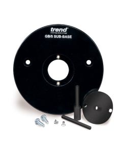
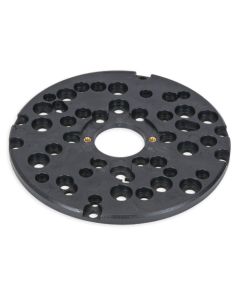
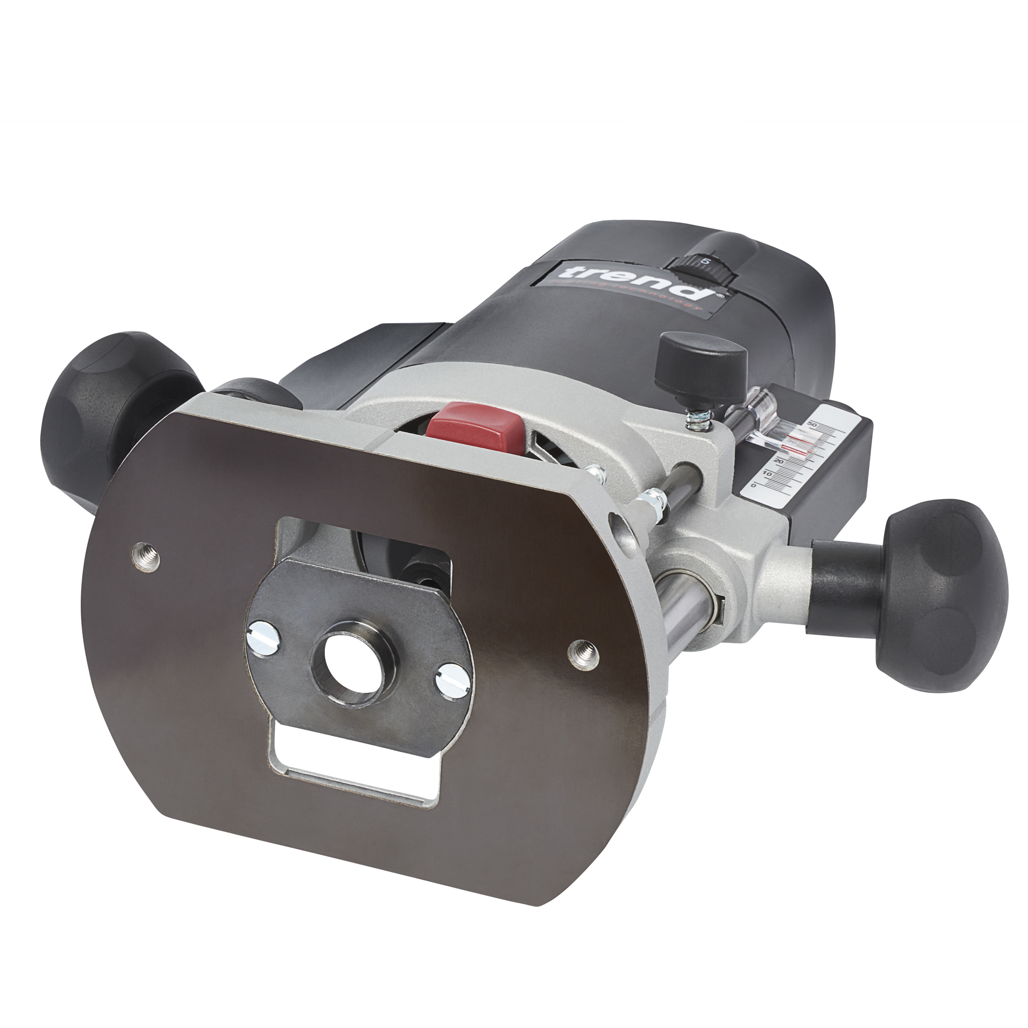
The Unibase enables routers with non-standard guide bush fittings to accept the range of Trend guide bushes. It will fit directly to most routers.
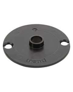
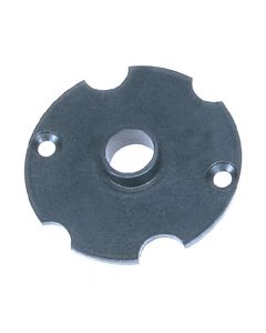
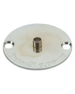
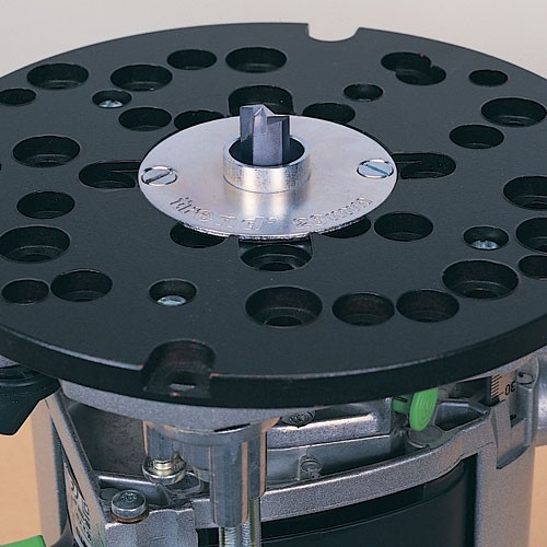
The UNIBASE comes with a Line-up pin which is used with a 16mm plastic bush to ensure concentricity of the cutter to the guide bush when fitting the sub-base.
The Line-up pin suits collet sizes 1/4", 8mm, 12mm and 1/2".

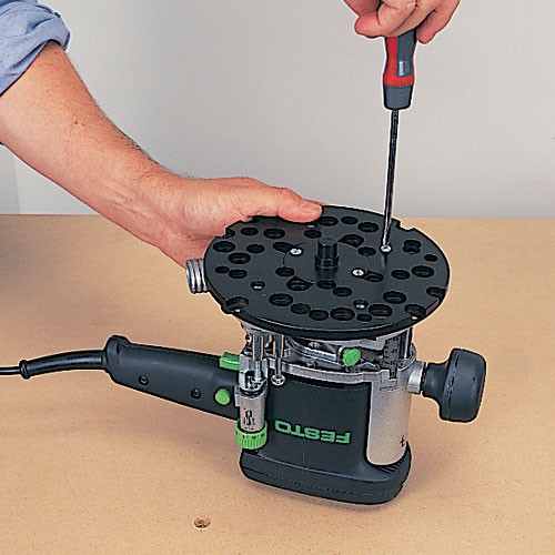
Fitting the UNIBASE
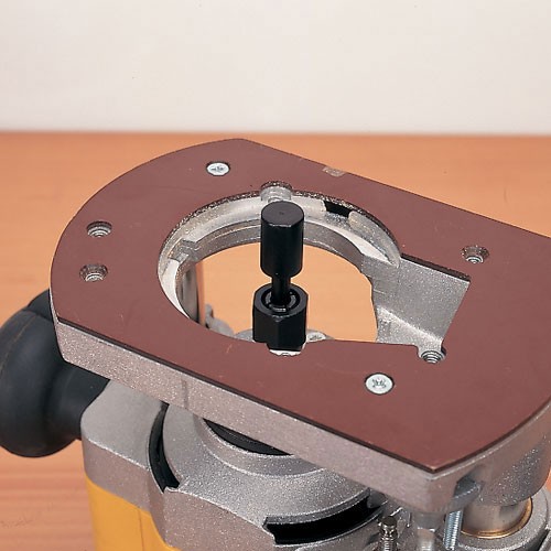
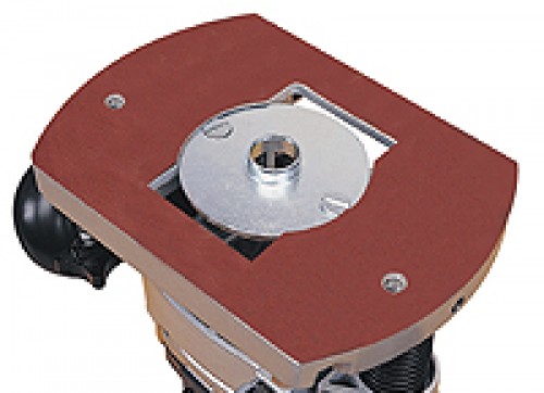
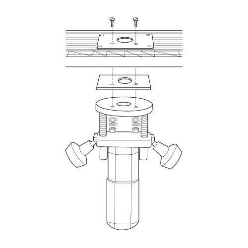
First fit the line-up pin into the collet and plunge it through the router base.
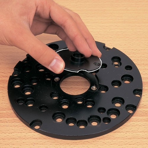
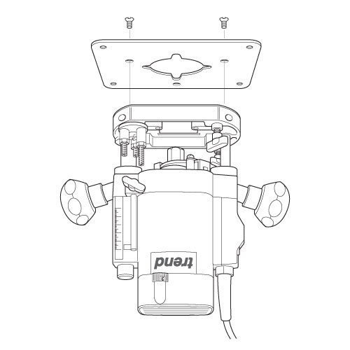
The 16mm plastic bush is then fitted into the UNIBASE and secured with the countersunk screws provided. Identify the correct fixing holes for your router using the instructions provided. Then place the UNIBASE over the line-up pin and rotate it in order to line up the fixing holes with the holes in the base of your router.
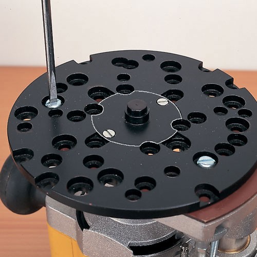
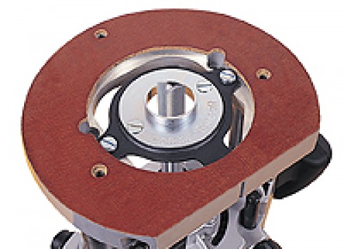
Secure the UNIBASE with the screws provided and then remove the 16mm plastic bush.
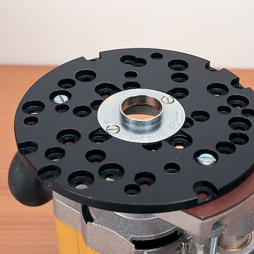
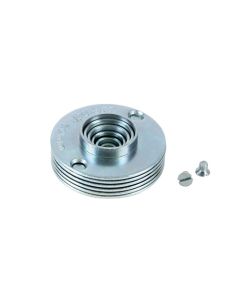
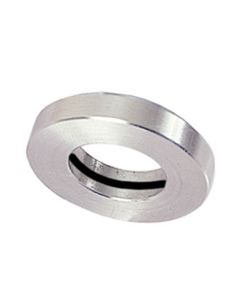
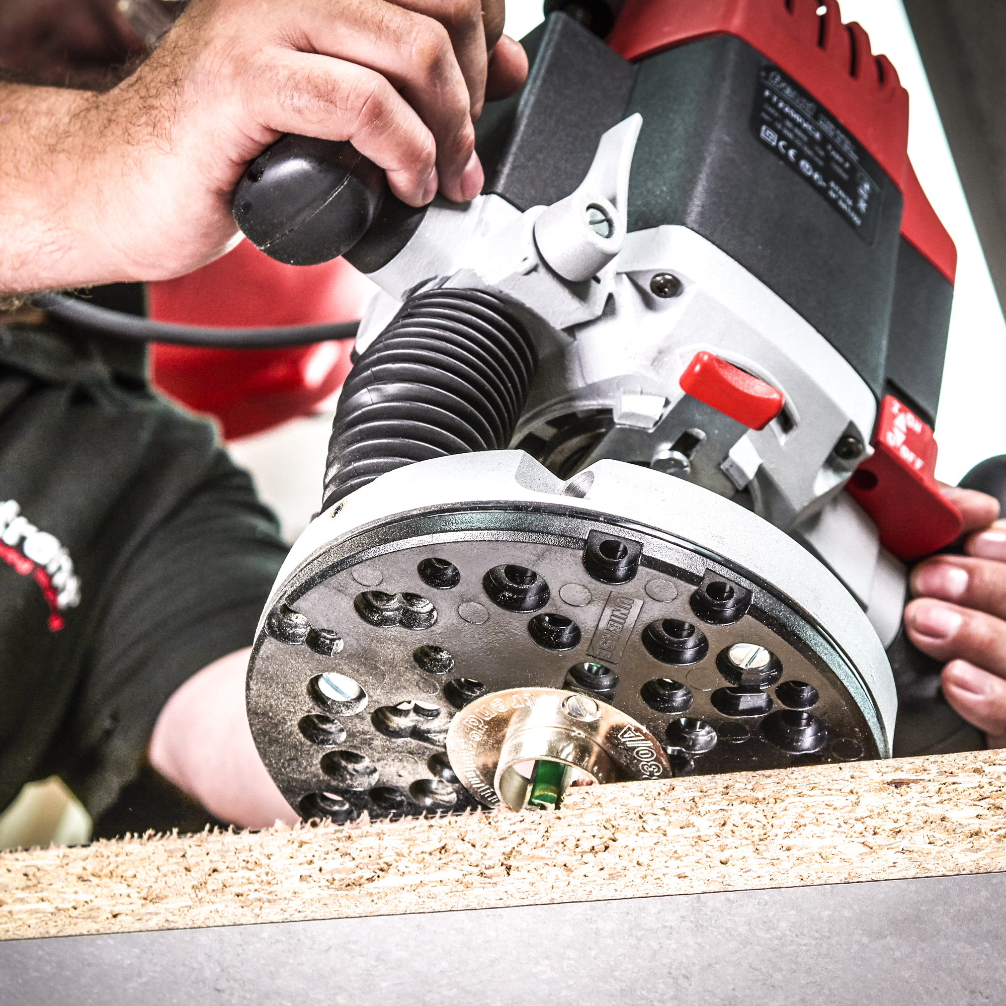
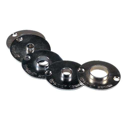
Any size of Trend guide bush, steel or plastic, can now be fitted. These range from 10mm up to 32mm (GB10 - GB32). For larger diameter cutters a 40mm guide bush (GB40) is available
Trend Unibase Universal Sub-base Overview
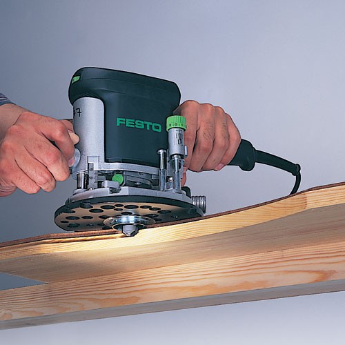
The use of templates and guide bushes opens up a huge number of possibilities for router users. Cutters with a bearing guide on the end can only be used on the edge of a workpiece. However a guide bush places the guiding method above the cutter, allowing the workpieces to be routed either on the edge or in the centre.
Different diameter guide bushes are needed to suit different applications and router cutters. Here lies the problem. Most router manufacturers do not offer a wide range of guide bushes and each size and method of fitting differs from one manufacturer to another. Often guide bushes for a particular machine can be difficult to source and various jigs require a specific size of guide bush.
The UNIBASE offers a solution for owners of most makes of router. Made from injection moulding plastic, it is formed with a range of hole positions to allow it to be fitted to all popular makes of router, using the bolts or screws provided. It is also supplied with two line-up pins with shank sizes for both imperial and metric collets and a 16mm line-up bush. These allow the UNIBASE, fitted with the guide, to be aligned concentric to the cutter.
Guide bushes ranging from 10mm to 32mm in 2mm increments and a 40mm bush are offered to give flexibility in the choice of router cutters for specific applications. Please note, the UNIBASE is not required for Trend routers as bushes fit direct into the router base.
Templates can be made from plywood, MDF or plastic. The material should be hardwearing, stable and easy to machine.
The thickness of template must be sufficient to prevent the template ring from touching the workpiece, but not so thick as to cause a loss of cutting depth. A thickness of 6mm or 1/4 inch is ideal.
A guide bush consists of a projecting ring of a specific diameter, fitted to a mounting flange. Fitted to the base plate of the router, the guide bush ring projects beneath the base by approximately 5mm. The cutter is then free to revolve concentrically within the ring, as the outside edge of the ring follows the template contour. Due to the difference in diameter between the guide bush ring and the cutter, an offset or margin must be allowed for when setting and cutting out the template.
TBC Router Base Standard and what it means

There are many routers on the market and a multitude of accessories designed to fit them. Unfortunately, a number of different fixing hole positions have evolved, both for the guide bush and for securing the router base to a table or jig. One particular format often referred to as the Trend/Elu configuration emerged as the ´defacto´ standard, and was adopted by other manufacturers in the early days, notably on some Bosch and DeWalt routers. This was later defined as the TBC standard and a TBC logo was then used to identify routers jigs and accessories that conformed to this standard.
The TBC router base fixing format originally was introduced on the Elu MOF 11 and MOF 31 in the early 1970´s to enable these machines to be mounted in a router table and to fit various Trend accessories. The guide bush fixing format came about when the MOF 96 was launched in 1974. Trend have developed accessories for these Elu routers over a period of 40 years and although most of their accessories will fit other makes, the primary fixtures tended to be for these machines. When Trend later introduced their own range of routers, they naturally incorporated the TBC configuration.
We recommend that router users buy routing products conforming to this standard to reduce duplication of accessories and to prevent modifications being required to the base of the router, table or jig.
Then if a number of different makes of router are owned, only one set of guide bushes would be required. Router tables or jigs would only need one set of fixing holes. And it would become unnecessary with certain makes of router, for the router base to be modified or drilled to suit a router table or jig.
However for router owners wishing to purchase the Trend range of guide bushes, the Unibase is available. This is pre-drilled to fit all popular makes of routers.
The exact dimensions for the configuration are as follows:
The guide bush recess should fit a guide bush 60mm in diameter with two 5mm countersunk holes at 50mm centre to centre. Thickness of guide bush plate should be a maximum of 2mm and spigot projection a minimum of 6mm.
Router table fixing positions should have either 2 or 3 M6 fixing points. The 3rd apex hole need only be used for larger heavy duty routers.
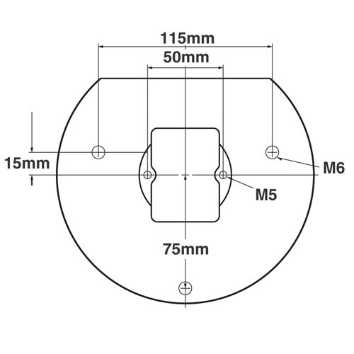
Dimensions for these tapped holes are as shown.
How to re-drill an adapter base or sub-base
With some makes of router, it may not be possible to drill the sub-base to allow direct fixing. If this is the case, the sub-base will be supplied with two M6 pan head screws, and will require alternative fitment.
Alternative Fixing Methods
1. If the router base will accept a nut and bolt in the position of the drilled sub-base holes, centralise the sub-base on the line-up pin, mark hole position through it, and drill out the router base.
2. If the router base is made from aluminium or plastic with a thickness of 6.35mm (1/4¨) or more, an M6 threaded hole can be tapped in. The position for tapping the holes, should be marked through the sub-base after centralising it.
3. Should there be no fixing points and bolt fixing is not possible or desired, double-sided tape (Ref. DS/TAPE) can be liberally applied on the sub-base can be used to hold it in position. Tight clamping is needed to make sure tape is securely mated.
Periodically check sub-base is concentric to collet and reset if necessary.
How to re-drill a Fixing Plate
- Remove the plastic base of the router. Alternatively a photocopy or an outline of the base can be made of the plastic base instead.
- Draw cross lines onto the plastic base of the router.
- Draw cross lines on the fixing plate with a pencil. These cross lines should bisect the plate on both sides.
- Align the lines on the fixing plate with those on the plastic base and secure the fixing plate to the plastic base.
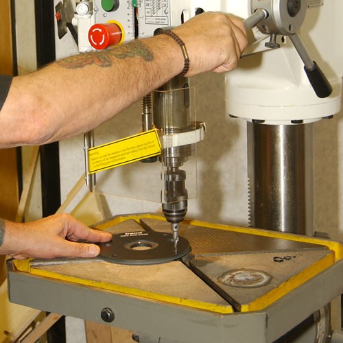
- Using a centre punch, mark the centres of holes.
- Drill the required hole size with a suitable metal cutting drill bit. Best results will be obtained if your power drill is mounted in a drill stand.
- Countersink the hole with a countersink bit to a depth so the heads of the screws are slightly below the top surface. Clean off any burrs created.
- If you do not have the necessary equipment to carry out these operations, then a local engineering shop will be able to carry them out accurately for you.
Some routers may require the removal of the plastic base slider to allow fitting to plate.
Special note for Bosch POF routers
For the Bosch POF range of DIY routers a packing piece must be made in 3mm to 6mm thick plywood or MDF. This is then placed between the underside of the plate in the table and the underside of the router base. The fixing screws can then be used. Enlarging the aperture in the base of the router is also advised if large diameter tooling is to be used.