We use cookies to make your experience better. To comply with the new e-Privacy directive, we need to ask for your consent to set the cookies. Learn more.
Framed Door Routing Project
A traditional framed and panelled door created to a really professional standard with ease.

Profile scribing and raised panel moulding cutters are widely available and relatively inexpensive if you buy them as sets, so it is now possible to produce traditional framed and panelled doors to a really professional standard with ease.
Step 1 - Cutter Selection
Before we start, it is as well to clarify the terminology of this job as many of the component names seem to be used rather haphazardly. The sides of the door are called stiles and as well as being strong enough to support the door they must be able to take any ironmongery in the way of hinges and catches.
The top and bottom components are called rails, the top one may be parallel, or sometimes it is shaped into a cathedral or cambio pattern. If it is a big door there may be an intermediate stile which in this case is called a muntin. The rails are jointed into the stiles with a scribed joint which matches the decorative stile edge.
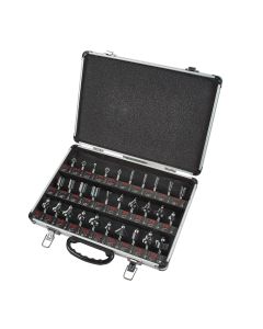
The cutters are produced in a wide range of shapes and styles and are ideally suited for the 1/2 inch router as they tend to be on the large size. However there is a more limited selection available with 1/4 inch and 8mm shanks so this technique should be within the reach of anyone even with a lower powered router.

In this case you will need at least 750 watts and work with care to avoid overloading the router and cutters.

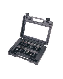
For this exercise I am using a cutter set produced by Trend which consists of an interchangeable profile and scribe cutter and a separate profile cutter.

The panel in the centre of the door can be solid or veneered ply or MDF, and may be flat or raised into the traditional fielded shape. The actual mould varies from a plain bevel to an elaborate profile. The other edge of the panel is sized to fit into the groove that runs all round the inside edge of the door.
If you are making a cabinet with no centre divider to from a stop behind the meeting stiles of the two doors, the edges are usually rebated to form an integral stop.

The only snag with this is that the two stiles now appear to be of uneven width, so use a bead cutter to form a false groove down the wider section and restore the balance.

The profile scribing cutter is made up from several components all of which are held on a precision arbor. The groover is normally standard at 6.3mm but a 4mm one is available if you are using glass or mesh panels. Having cut the scribe on the rail ends the profile block and groover are rearranged to cut the matching profile and panel groove along the inside edges.

As you assemble the cutter make sure that the cutters are positioned at 90¡ to each other on the arbor to minimise vibration and produce a more even cut, they bare not necessarily correct when you buy them.
Shims enable you to make fine adjustments to the tightness of the joint and make allowance for any subsequent sharpenings

As the setting for this whole procedure is quite critical it is essential that your router is fitted with a fine height adjuster so that you can match the profile and scribe cuts perfectly.

Also as the cutters are large, do ensure that at least three quarters of the shank is gripped in the collet to resist the high rotational forces involved.

You can also help here by using a lower speed for the very big cutters where the peripheral speed would otherwise be too high. You will need to reduce to something like 15,000 revs.
Step 2 - Timber Choice, Marking Out and Table Work
Before you start, it is essential that the timber is good quality and properly prepared by thicknessing to a constant dimension. The joints will never fit properly if there is even the slightest variation in size.
The thickness of the rails and stiles should be in relation to the overall door size and will therefore affect the choice of the cutter.

As the setting up procedure is very much trail and error, always prepare a couple of spare pieces to allow for a few trial cuts.
Frames for larger or heavier doors need to be 20 to 24mm thick, though 18 to 20mm is more normal for small cabinet doors. The width is usually around 40mm though this may vary on the top rail if it incorporates any shaping.

The length of the rails needs to be calculated to allow for the stub tenon that is formed on either end.
The cutter set I am using forms a12mm tenon so the calculation is: overall width of door minus 2 x the width of the stile plus 2 x 12mm.

The actual machining process must be carried out using the router mounted in a table, you cannot do it safely or accurately enough using the router hand held. Connect the table to a suitable extractor to minimise the dust produced as you work, this is particularly important id you are using MDF.
This dimension has to be determined exactly at this stage; you cannot trim it in any way once the profiles have been cut.
At all stages use the hold downs and feather boards to control the work safely when it is in contact with the cutters, though please note that these guards have been removed for clarity in some of the photos. It should also go without saying that all adjustments and cutter changes are carried out with the router unplugged.

The normal sequence of operations is to start with the scribe joint on the rail ends and for accuracy it is better to make up a guide jig for this. Even if your table has a sliding table it is still better to use the jig as it also minimises end spelching as the cutter breaks through. The jig is just a piece of 6mm MDF onto one end of which is glued a piece of 50 x 25mm to act as a stop.
The only critical requirement is that this stop is at a perfect 90 degrees to the edge of the MDF. Obviously this stop gets cut as it passes through the cutters, and you will need to cut the resulting profile away if you change the shape, so make the overall jig quite wide to allow for several trimmings.

Make sure that the fences of the table are in line with the bearing on the cutter using a steel rule to line it all through, If the fences are adjustable as well, close them up to leave them approximately 2mm clear of the cutter.
Set the height of the cutter to leave a minimum quirk on the moulding of at least 1.5mm. If it is less than this the edge will be weak or be lost when sanded or painted.

With everything set and locked securely clamp the rail to the guide jig, making sure that both of them are tight up against the fence.
Step 3 - Routing Application
Once everything is set and locked securely, the routing can take place.

Then slowly push the whole assembly through the cutter in a smooth action that is not too slow or the cutter will burn the timber.

Make sure the edge of the guide jig stays in contact with the fence all the way through, and keep cutting right into the end of the stop. This should prevent any breakout and the resulting joint should be really clean.

Repeat the procedure on the ends of all the rails keeping them orientated correctly.

You can now rearrange the cutter set for the matching stile edge profile, This is best done with the router in situ using the spindle lock to help you undo the nut, but do remember to unplug first.

Use the scribed rail end as a guide to reassembling it all, then make a trial cut in a piece of spare material, You may need to insert one or two of the shims to tighten or loosen the joint, and then adjust the cutter height to leave the rail and stiles faces flush.

Once all this is set, run the mould down the edges of each of the stiles and the rails making sure they are held firmly on the table or the groove will end up out of line with the edge.

The rails and stiles should now fit together perfectly.

The panel is next but there are a couple of important considerations here. Firstly, if you are gluing it up from several pieces arrange then in such a way as to minimise any cupping. This is normally achieved by alternating the ring orientation on adjacent pieces. Secondly, if the panel is solid wood you will have to make some allowance for it to move with changes in humidity. Any shrinkage and expansion will be greater across the width of the panel so leave about 3mm gap at either side and 1mm at either end. If you are using man made panels where movement isn't an issue, just allow 1mm all round.

Also bring the fences up close as well and lock them tight. Revolve the cutter by hand before you switch on just to make sure there really is enough clearance. Level the fences through on the cutter bearing in the same way as for the rail scribe.
The panel raising cutters are necessarily large diameter so they may not fit through the aperture in your router table. If this is the case make a false table from a piece of MDF and bury the cutter into this to achieve necessary height adjustments. If the aperture is big enough insert a suitable ring to ensure maximum support fort the work.
Step 4 - Assembly of Frame and Finishing Touches
The final stages of the project involves constructing the door and making final adjustments.

Now with the router slowed down to a suitable speed for the diameter of the cutter, make a shallow pass across the two ends of the panel and then down the sides to remove any breakout.

Keep increasing the depth of cut until the lip formed on the edge of the panel is a nice sliding fit in the grooves on the frame.

Make a trial fit of the whole assembly just to check everything is in order and that the panel will not stop the scribed joints from closing up.

If everything is OK glue the frame joints and clamp the whole thing together making sure it is square. You do not normally put any glue on the panel edges but leave it loose to allow for any movement. If it is too loose use a tiny veneer pin or two put through the stile and panel from the back to stop it slopping about.

A light sanding once it is dry will flush off the joints and remove any glue smears and you can leave your door at that.

However for most situations where the doors are being hung singly, it looks better if you run a suitable complementary mould round the outer edge of the door to make them look a little lighter.
When you come to applying the finish remember to do exactly the same to both sides of the panel or you will set up differential shrinkage problems that will cause it to try and bow.

This is the completed Framed Door Routing Project.