We use cookies to make your experience better. To comply with the new e-Privacy directive, we need to ask for your consent to set the cookies. Learn more.
Dished Shape Clock Routing Project
Making a beautiful dished shaped clock with a router.

We are showing how this beautiful dished shaped clock can be produced almost entirely with a Trend router.
The clock illustrated is 250mm in diameter and is shown alongside a slap of seasoned oak, 40mm thick, from which the clock will be produced.
Step 1 - Preparation for the Project
The first step is to draw an outer circle indicating the position for cutting a square shaped edge, and then cut to size.

For this purpose, a a self-made compass can be simply made from two identical arms hinged at one end by an M8 bolt/nut. The other ends have slots into which a pointed rod is inserted in one and a standard ball point pen inserted in the other one.

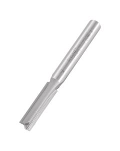
With circle drawn, the workpiece is then cut with a square edge either by router, hand held using a beam trammel and fitted with a 1/4¨ diameter long reach cutter Trend Ref. 3/22 or on a router table as suggested for producing the rounded top edge of the clock below.

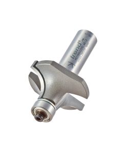
To machine a radiused profile on the face edge of the clock, a router table is the best option. Left photo shows a T5 router mounted beneath a PRT Router Table. Router has been fitted with a self-guiding rounding over cutter Trend Ref. 46/150. This cuts a 12.7mm (1/2¨) radius around the clock edge. In operation, the workpiece is rotated anti-clockwise with bearing engaging the vertical edge of the workpiece.
Step 2 - Routing
To produce the concave dished shape on the clock face, the workpiece is first fastened to a slow rotating chuck plate which rotates at approx 5 revolutions per minute. This being powered by a standard geared motor.

The shaping procedure is obtained by mounting a T5 Trend router between a purpose made gantry from which the router is swung backwards and forwards. The radius of the swinging arm is set to produce a concave shape to the full width of the front face.

In operation, the depth of cut is gradually increased by turning gradually both knobs mounted on each arm of the gantry.

Note the radiused base of the cutter especially chosen for machining the concave shape on the clock face. Its radius is 12.7mm Trend Ref. C058X1/4TC.
Here we see the finished dish shaped clock face ready for the next step of inserting 12 mushroom shaped pellets around the outer edge of the clock.

Twelve mushroom shaped pellets are to be recessed into the perimeter of the clock face to display the 12 hours in the day. To set the positions of the pellets, a paper pattern is placed over the clock face and the 12 positions marked for the next operation, namely, the drilling of holes to receive the projecting stems of the pellets.

Following the marking of the 12 points on the clock face to receive the pellets, the actual drilling of the holes, 3 mm deep, can take place.
Step 3 - Finishing
Additional features must be added to finish the design and gain functionality.

There are two sizes of pellets which require two sizes of holes to receive the stems of the pellets.
Four large pellets are 10mm in diameter and need holes to receive them - 8 mm diam.
Eight smaller pellets are 8mm in diameter and need holes to receive them - 6 mm diam.
These button pellets can either be bought in or self-made from dowelling, but the above procedure was found ideal for this project.

The clock is powered by this small square shaped electric motor and tubular battery.
Feedback confirms that replacement batteries are needed rarely within a year.
Motor size is 60mm x 60mm by 16mm deep and a recess of this size or more is needed.
Clocks are available normally with three sizes of spindle lengths and securing flanges.
Special Note: The depth for routing out the recess is critical relative to the choice of model.
Reason.: The wall thickness of the clock to receive the motor should be between 3mm and 6mm thick to ensure the clock is firmly mounted within the clock frame.

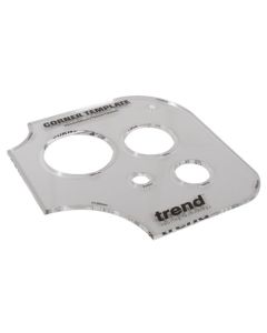
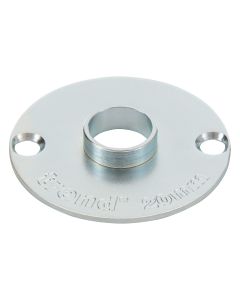
To rout a recess in the back of the clock, a template was selected from the Trend range, namely Ref. TEMP/COR/A. This was secured centrally exactly over the hole in the clock. The 100mm aperture on the template was chosen. This size being ideal to receive the 20mm diameter guide bush Trend Ref. GB20, fitted to the base of the T5 router. The cutter used was 16mm in diameter with a 25mm cutting depth Trend Ref. 4/26.

When routing the recess, cutting depth should gradually be increased to ensure the timber wall thickness is no less than 3mm thick and no more, preferably than 5mm thick. This is critical for tightly mounting the motor in the back of the clock using the securing flange described below.

The assembly of the clock motor can now be inserted into the 100mm circular recess cut out with the router.
It is secured in place with the brass flange as shown. With variations in wall thickness, any slack can be overcome by fitting washers of suitable thickness onto the shaft between the motor and the timber face.
A. Brass Flange: This screws into the central threaded hole in the back of the clock.
B. Flange: Is shown in place, having been threaded onto the clock beneath, via the 10mm hole in the centre of the clock.

The completed Dished Shape Clock Routing Project.
By Jim Phillips