We use cookies to make your experience better. To comply with the new e-Privacy directive, we need to ask for your consent to set the cookies. Learn more.
Guiding The Router
The ability to guide the router the way you want it to go is essential and there are several accessories available to help you. Some are provided with the machine itself, whilst others have to be made or bought as extras, but they all contribute significantly to the productivity and versatility of the router.
Routing with the side-fence

The side-fence or edge guide is used when you are machining grooves or mouldings either along, or parallel to a straightedge of the workpiece.
It is usually supplied with the router and varies in construction from being a simple piece of pressed steel to a more sophisticated aluminium casting with built- in micro-adjustments.
As the side-fence is such an essential part of the router, it is important that you take a good look at this as well when you are choosing the router itself.
Although each side-fence is usually designed specifically for its own particular make or model of router there are third- party versions available designed to fit all popular routers, e.g. the Micro fence.
These often represent a significant investment, but they can offer increased accuracy and versatility over the standard guide.
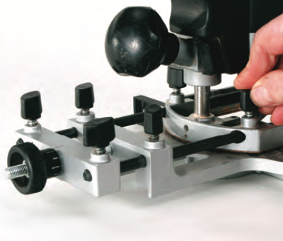
Typically, the side-fence is fitted to the router with a pair of parallel metal rods which slot into the base plate, and it can then be locked in place with clamping screws in both the fence and base castings.

Better quality fences are fitted with false plastic facings held by recessed screws. Facings are slotted and adjustable so you can reduce the gap between their inner ends and the cutter. Closing the faces in this way reduces the risk of the fence pulling in at the start and finish of a cut. However, you must allow sufficient space for the waste to clear quickly and freely from around the cutter, 2 or 3 mm should be sufficient.
This arrangement also means that the standard facings can be removed and replaced by custom-made wooden versions for special applications.

The maximum distance that a cut can be made from the edge of the workpiece is determined by the length of the rods supplied.
This distance can be increased by substituting longer rods of the same diameter, or by using extending rods that screw together.
However, if the length becomes excessive they tend to flex, causing the cutter to leave a distinctly rippled effect.

A side-fence can be somewhat clumsy to use and some practice is needed to apply it smoothly every time. The protruding ends of the fence rods and even the fence itself, need a significant amount of working room, so always do a dummy run with the router switched off to make sure there will be no obstructions when you come to make the actual cut.
Clamps are notorious for getting in the way and also check that the power cable is clear and cannot become trapped in the fence.

When you’re using the side-fence, the feed direction of the router should always oppose the direction of cutter rotation to keep the fence pulled in hard against the work. However, it may sometimes be necessary to use the back cutting technique already described for some edge trimming or moulding operations.
This is quite acceptable provided cuts are only light, but as the rotational action of the cutter is now trying to pull the fence off line, this technique should never be used when cutting grooves or panel moulding.
Positioning the side-fence for cutting grooves and housings

Mark out the position and width of the cut on the face of the first workpiece. Place the router on the face of the work and lower the cutter until it just touches the surface. Turn the cutter by hand until the cutting edges are aligned at right angles to the face of the fence.
Now position the cutting edge against the marked line, and slide the fence up tight against the edge of the workpiece. Tighten all the clamping screws on both fence and router, making sure that the cutter remains on the line as you do so.

An alternative way is to measure the required distance between the fence and the nearest cutting edge, but always remember to measure to the actual cutting edge rather than the body of the cutter as these are not the same diameter.
Check the setting by placing the router over the work and lowering the cutter onto the surface. If there are several identical pieces to be machined, it is only necessary to mark out the first piece, as the fence settings will reproduce the same cut on subsequent pieces.

For really fine adjustments of the fence some form of micro adjuster is essential. If this is not a standard feature of your fence it is usually available as an optional extra, so again check availability before you buy a particular model of router.
Although the design of micro adjusters varies, they all work on the same principle and allow you to make minute adjustments that are difficult to achieve by manually sliding the fence along the rods. Sometimes just the act of tightening up the locking screws on the fence is enough to move it slightly out of position. A micro adjuster overcomes all of these problems.
Positioning the side-fence for machining the edge

First set the cutter against the marked line and then bring the fence up into position. Adjust the fence facings to allow a sufficient gap for waste material to clear from the cutter.
If you have to machine a deep profile that forms an undercut it is impossible to make several passes by adjusting the cutter vertically. Instead, the cut has to be worked in progressive horizontal steps resetting the side-fence to increase the width of the cut on each pass.
Maintaining contact between the side- fence and the work is not critical when you are edge moulding, as any deviation will not affect the finished profile, as it
can be corrected by making a second
pass.

However, as we already seen, if you’re cutting grooves or mouldings within a board but parallel to the edge, any deviation will deflect the cutter away from the line of the cut and spoil the work. Using the fence on the correct side of the router relative to the direction of rotation is obviously the main factor here but also ensure that the edge of the work is square and flat.
Drops of glue or resin, or even areas of raised hard grain are enough to cause both fence and cutter to deviate off line.
Always maintain an even and constant pressure on the side-fence, keeping it against the edge of the workpiece whilst making the cut.

No matter how careful you are in using the side-fence, it can still catch you out occasionally, usually at the beginning or end of the cut.
The usual tendency is for the router to turn in, as there is relatively little support for the fence in these areas, but there are several strategies you can adopt to overcome the problem.

By leaving adequate waste at each end of the work that can be cut off after making the cut.

By temporarily clamping waste battens at either end of the work which also eliminates break out when you’re working across the end grain.
By fitting longer wooden faces to the fence. If you’re using a relatively large edge moulding cutter, replace the existing faces with two separate longer ones.

However if you’re making small mouldings that do not cut across the full depth of the workpiece, a one-piece fence can be fitted and the cutter plunged part way into it. This produces a continuous fence that minimises the possibility of the cutter turning in. However, there can sometimes be a problem clearing the waste with a one piece fence, so it may be necessary to cut an additional clearance slot.
The same problem can occur at the start and end of the cut in the vertical plane, as the cutter aperture in the base plate drops off the end of the work. This is usually a matter of technique and with a little practice you subconsciously adjust your grip to compensate.
If you are struggling with the router tipping and a particular cut is critical, clamp a long batten alongside the work to support the router beyond the length of the cut edge. This is a particularly useful tip if you are trying to work on the edge of a very narrow workpiece.
Making the cut
1) Check that the edge of the workpiece is straight and free of any high spots and make sure it is clamped firmly to the bench. Any end, or waste battens must be flush with the top face.
2) Set the depth of cut to make the first shallow pass and then use the turret stop to set the final and intermediate cuts. Adjust the position of the side fences and make sure all clamping screws on both the router and fence are fully tightened.
3) With the cutter clear of the workpiece, apply gentle pressure against the front section of the fence. Switch on and allow the router to reach full speed. Start the cut, keeping the full face of the fence against the edge of the work and maintain a constant feed rate. At the end of the pass, reverse the pressure onto the rear section of the fence to prevent the cutter turning in at the end of the cut. Switch off only when the cutter has left the work and then allow the router to stop before lifting it clear.
Modifying the side-fence

Occasionally the edge profile you are producing may require the addition of an auxiliary face to the side-fence in order to maintain sufficient support.
E.g. When cutting a deep profile that will leave an inadequate guiding edge that may not even be line with the fence itself. In this case, screw on a deep fence and run this against a secondary guide edge fitted below the workpiece.

Similarly, if the profile ends up cutting away the full face of the edge, for instance when you’re rounding over or edge planing, you have to modify the fence by fitting a false cheek to the rear portion.
Ideally, this should be profiled to be an exact reverse of the moulding but if this is difficult it is usually possible to use a simpler profile to bridge over the detail.

In the case of edge planing, the rear portion of the fence is fitted with a thin spacer to make it about 2mm thicker than the front fence.
The cutting edges then need to be aligned perfectly flush with the face of the front fence to produce a cut the same thickness as the spacer

For really accurate positioning of mortise, housings or grooves, the addition of a second side-fence positioned on the opposite side of the work, makes the job foolproof. You may be restricted in this by the length of the support rods, although you can replace the standard ones with longer ones.

If you are using the double fence technique, do make sure that the faces of the workpiece are parallel and the top surface is flat and be aware of the router tipping at the extremities of the cut.
If you need to widen a groove and are just using a single fence, always make the second cut by moving the cutter away from the edge of the work, i.e. to the left, and then feed the router against the rotation of the cutter. Now any deflection of the cutter will be into the pre-cut waste area rather than into the edge and face of the work.

If a groove has to be perfectly centred across the width of the work, use a cutter slightly narrower than the required width and make the first pass.

Then turn the router round and make a second pass in the opposite direction. Use the same principle for putting in a series of flutes or parallel grooves, working from either side of the work each time.

Alternatively, use a self centring base. In certain cases, the side-fence can also be used to guide the router against a curved edge. For this, it is necessary to fit a shaped block to the fence, which is either cut to match the radius of the curve, or designed to support the fence against the guide edge at two points only.
Fence maintenance

For accurate setting it is important that the fence slides smoothly on the rods so these need to be cleaned periodically to remove sticky resin deposits.
Another problem is that repeated use of the clamp screws can sometimes raise burrs on the surface of the support rods. These should be removed with a very fine file or fine abrasive paper.
A quick spray over with a dry silicone lubricant will ensure the rods slide easily in both the fence and the router base plate. Check that all the clamping screws turn freely, as they sometimes become jammed with fine dust and the fence then appears to be secure when it is not. It is also important that the anti- vibration springs remain in place.
Straight line routing

Sometimes it is just not convenient, or even possible, to use the side fence for straight cuts. For instance you may be routing a groove across the face of a very wide workpiece and the bars of the side fence are just not long enough and would certainly be very unstable even if they were.
In this case, the router can be guided by a simple straight fence, such as a timber batten or clamp guide.
All routers are made with the baseplate concentric to the cutter axis, although some may also have one or two flat sides to ensure that the router will run against a straightedge.

Straight guides should always be made from a rigid material that is at least 8 mm thick. This will prevent it from flexing along its length and also stop the router accidentally lifting up over the edge. Stable materials such as MDF, plywood, or Perspex are ideal, and the guide must be wide enough to allow it to be held securely in position with suitable clamps that are out of the path of the router.
It must also be longer than the required length of cut to allow the router to be guided accurately at the entry and exit points of the cut and prevent it turning in.

To help you line up the straightedge accurately every time it can be fitted with a stock at one end, very much like a standard Tee square. You can buy ready made versions, but it is quite simple to make up your own. Make sure that the stock is long enough and fixed to form a perfect 90° angle.
Then, with the router running against the guide, machine a slot across the stock, (clamping it against a piece of scrap will help to minimise breakout.)

Finally, use a V cutter to put a centre line down the middle of the groove as an aid to positioning. Now all you have to do is align the groove in the stock with the centre line of the required cut.

Of course you can develop this idea further for cutting at an angle across the workpiece by attaching the stock to the straightedge at the necessary angle, either by screwing it in place for a permanent arrangement, or using a bolt and wing nuts for an adjustable guide.
No matter what sort of straight guide you choose, it is essential that it is clamped firmly in place. You can use standard G clamps, which are usually to hand in the workshop, but other clamps and holding devices are less likely to obstruct the path of the router and may offer a better solution. These include end socket and toggle clamps fitted to the ends or underside of the guide.

Ideally, use clamps that can be operated single handed, as you can then hold the guide in place with the other hand as you tighten up to stop it moving as the pressure comes to bear.
Clamp guides and tracks

Ready made clamp guides, consisting of low profile extruded aluminium straightedges with integral clamping systems, are one of the best options for guiding the router along straight cuts.
They are available in a variety of different lengths and the simple clamping action allows the guide to be fitted quickly, whilst the low profile presents little obstruction to the path of the router.

As these guides are mainly intended for use
with square edged workpieces, they may not always be able to grip properly if the workpiece is very thin or is already moulded along the edge, as in a kitchen worktop. In this case, deeper detachable jaws are available as an optional accessory.
Similarly, you can also add a squaring attachment that clips to the fixed jaw and allows more accurate positioning for 90° cuts.

To use these guides, adjust the jaws to suit the width of the workpiece before positioning for the cut. Then apply light pressure by lowering the locking lever half way and check that the guide edge is still correctly positioned. You can tap it gently to make minute adjustments before applying final pressure by lowering the locking lever fully.
Although not self clamping the Trend Varijig angle guide allows you to make precise angled cuts.

A more sophisticated version of this arrangement is the guide track system where the router is mounted on a sliding plate that fits into a Tee slot along the top of the track.

This is obviously a superbly accurate arrangement and the tracks are available in detachable sections of various lengths to suit virtually any application. They are particularly good when you are working with large sheets of material. The Trend Clamp Guides can also be fitted with stops to limit the router travel if you are cutting stopped housings, slots, etc.

Special Back-to-Back clips can be used to join two clamp guides which allows you to attach the guide directly to the bench and you can then use the top jaws to hold the work.
Positioning a straight guide

Start by marking out the position and width of the cut on the face of the work. If you are using a router with a flat sided base, turn the cutter so that the cutting edges are at right angles to the flat side.
Measure the distance from the cutting edge to the outside edge of the base.

Then measure off this distance on the workpiece at both ends of the cutting line, working to the left-hand side of the groove. Position and clamp a straight guide against these lines.
The procedure is slightly simpler if you’re using a round-based router as you can measure the distance from the cutter to the edge anywhere around the base.

The other way of positioning the guide is to stand the router on the face of the workpiece at one end of the required groove with the cutter’s edge against the cutting line. Mark the edge of the base plate on the workpiece, or even better, slide the edge of the straight guide up to it and lightly tighten.
Repeat with the base at the other end of the line, re-check the first setting and then fully tighten the clamp.
If you do a lot of work with a particular router/bit combination, machine up a piece of thin MDF or plastic to be exactly the same width as the distance between the edge of the router and the cutter and use this to position the fence clamping line.
Feed direction

When you are using a straight guide, always cut from left to right to maintain the correct feed direction, i.e. against the rotation of the cutter, as this will have the effect of pulling the router into the guide edge rather than allowing it to wander off line.

If you need to make more than one pass to get the required width of groove, make the second cut to the left of the first one to maintain this pulling action.

A very quick way to make multiple cuts without having to reposition the guide each time, is to use a thin spacer sandwiched between the guide and the router for the first cut and then remove it for the second one. This ensures that you can reproduce the same groove width each time.
On long cuts, be extra careful to feed in the correct direction as it is easy for the router to wander off-line as you change your stance to move down the work.

You can buy a special base for just this sort of application. The Trend Offset Trenching Base, allows you to cut wide grooves by varying which face of the base you run against.

Each face is offset from the centre by a different amount ranging from 1mm to 5mm. With this in place, you can cut six different groove widths with the same cutter and fence settings.

With the Trend CRB Jig, the built in micro adjuster gives a precise offset. All you have to do is position the clamp guide approximately, then adjust the router for position on the CRB and machine your groove. Simple! Also if you need further parallel grooves up to a max of 110mm centres you can leave the guide in position and just move the router on the CRB.
Cutting parallel housings

Sometimes, it is necessary to machine a series of equally spaced housings. This can be both difficult and time-consuming if you try and position the guide by measuring each time. Instead, just screw a spacer batten to the underside of the straightedge and the job becomes foolproof.

The spacer batten must be a smooth sliding fit in the groove and is fixed to the underside of the straightedge at the distance equal to the required housing spacing, less the base plate/cutter edge margin. It must also be perfectly parallel to the guide edge. Cut the first housing at the end of the work by clamping the guide across the workpiece with the batten uppermost.

Remaining housings are then cut by dropping the spacer batten into each previous cut. If you’re making matched components like a pair of bookcase ends, clamp each pair edge to edge and cut across both faces in one pass, to ensure they are identical.
Stopped housings

If you don’t want the grooves to run right across the width of the work, as for instance in a stopped housing, you can fix stops to the top face of the straightedge to limit the travel of the router.

This can either be screwed or clamped to the guide for a one-off application, or made to be fully adjustable by cutting a slot in the guide and locating the stops with a coach bolt and wing nuts. Make sure that there is a gap underneath the stop so that sawdust cannot accumulate between the base and the stop and cause a false reading.
Cutting across uneven surfaces

If you need to cut across an uneven surface it is obviously impossible to get the router to run smoothly and produce a consistent depth of cut.
In this case, make up a stepped straightedge by gluing together two lengths of relatively thin material, something like 8 mm MDF is ideal. Make one piece wider than the other by slightly more than the base plate to cutter edge measurement. Fix them together so that the back edges are lined up and then trim the bottom edge parallel to the top by running the router base against the upper edge.

The guide can then be used in the same way as the normal straight guide, clamping it at either end to bridge the uneven surface.
If you’re removing the waste or ground
from a flat area, such as a relief carving, the router must somehow be supported straight and level above the surface while the waste material is cut away and there are several methods for achieving this.

Here are a few examples:
1) On narrow surfaces the edges of the area can be left to allow the base to span between them.

2) On wider surfaces, the cutting operation can be planned to leave raised areas which are then cut away later by hand, or by fitting temporary support blocks over the cut face, or you can fit a large sub- base to the router to allow it to span over a wide area.
If this is cut from a transparent material like acrylic you’ll get a clearer view of the cutter.

3) If there is no support available from the workpiece, span it using ski pads fitted to the ends of the router side fence rods, but your bench must be absolutely flat for this to work accurately.

4) For extra rigidity if the cuts are likely to be heavy, make up a support frame and mount the router on an adjustable sliding carriage.
This can be made up quite simply using scraps of timber, although there are more sophisticated ready-made versions that fulfil a range of support functions if you anticipate extensively doing this type of work.
If you are removing a wide area that is recessed to an edge such as a half lap joint, always cut the shoulder first and then start the waste removal from the end of the work and gradually move the cutter inwards to ensure that half the router base is always firmly supported. Working the router in the opposite direction will gradually reduce the support, eventually causing the base to drop into the cut.
Straight cutting with a guide bush

Sometimes a groove has to be really precise and simply relying on running the base of the router against the straightedge may not be accurate enough. There is always the chance of a tiny amount of wander if the router is not kept firmly against the guide throughout the cut.

To avoid this, make up a straight guide with a slot cut along its centre line to take a guide bush, but the cutter/guide bush combination must be carefully matched to produce a free running slot with no side play.
Frame guides

If you need precision, along with a degree of versatility and do not want to use a guide bush, then it is useful to make up a frame guide by linking two straightedges together to form a square routing frame.
This allows you to cut wide housings or slots, by spacing the two straightedges slightly wider apart than the width of the router base. Remember to feed the router against the cutter rotation to ensure the router is kept firmly against the guides at all times. Any waste between the cuts can be removed using the router freehand.

A further refinement of this idea is to make an adjustable wooden frame using coach bolts fitted with wing nuts. If the straightedge and their linking pieces all have suitable slots cut along them, the frame can be setup for a variety of different cuts and you can also add clamping lugs to simplify mounting the frame, as well as sliding stops for cutting stopped housings.
The router base can either slide directly on the frame members or fit it to a sub-base. The slotted arrangement of the fences also allows the guides to be set at an angle across the workpiece and the frame can
be used to cut louvre and angled housings across the work.

The Trend Varijig, a highly accurate and adjustable frame, is available in a variety of different forms.
This system allows precise cutting of rectangles & squares, grooving & tenoning.
It also incorporates an anti-tilt block for the router if you decide to use it with a guide bush rather than guiding with the router base itself.

All these grooving cuts are effectively inside cuts, with the router bit cutting both sides of the groove and they rely on the router being held firmly against the edge guide.
If you do not concentrate fully during this operation or the guides become loose in anyway, the cutter will go off-line. This sometimes happens if the density of the workpieces suddenly varies, for instance if you hit a particularly hard knot. Whilst there is relatively little danger to the user, the cut will not be what you intended and will probably wobble off line.

For this reason it is sometimes beneficial to make the cut with two different diameter cutters, the first one slightly narrower than the second one, as the light cut from the second pass is less likely to be deflected off line and there is also room for the chips to escape cleanly as well.

A Tenon and Grooving Jig is another very neat and flexible jig that can be used for a variety of grooving and cross-cut work with circular saws or routers, it uses the same extrusion profile as the varijig.
After clamping the guide in position, always check with a square or mitre gauge to ensure that the position is still perfect and has not moved slightly during the clamping.
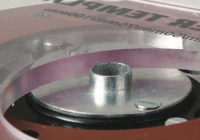
Working with guide bushes

The guide bush is perhaps the most useful way of guiding the router, and widens the scope of the handheld router for both amateur and professional user alike.
They are used in conjunction with an straightedge, jigs and templates and sometimes even just the edge of the
work itself, to produce both curved and straightedge work. They can also be used for cutting out, trimming or decorative edge moulding and offer the facility for cutting panel mouldings and other recessed surface applications. They are also used with a wide range of templates and jigs for such applications as comb jointing, dovetailing and cutting tenons.

The guide bush is effectively a small ring fence and stands proud of the underside of the router base plate. On high quality routers they are designed to be a precision fit and concentric to the cutter to ensure that there is always a constant distance between the cutting edge and the template during use.
Whether the guide is a straightedge or curved template, this constant margin is vital so that the guide bush faithfully reproduces the shape.

They are also used with jigs for precision drilling using all the advantages of the plunge action of the router, e.g. for dowel drilling or hinge sinking.
For precise working, the guide bushes need to be accurately manufactured in steel. This obviously makes them expensive, particularly if you require a range of different sizes.

However, there are less expensive plastic sets available for less demanding work or if you only need to use them occasionally. In this case, you get a set of 12 different bushes for the price of 3 or 4 steel ones.

One of the snags of fitting the guide bush is that the mounting plate can compromise the effectiveness of the dust extraction facility by effectively blocking off the cutter from the point of extraction.
To overcome this problem, some manufacturers supply bushes with a skeletal form to minimise any obstruction and maintain the necessary airflow.

In order to accommodate different diameter cutters, guide bushes are available with outside diameters ranging from 8 to 40mm. By using different combinations of cutters and guide bush diameters, you can easily vary the dimensions of the finished workpiece.
This is particularly useful for cutting stepped recesses or variations in fluting or panel moulding using a single template.
Adapters and sub bases

Not all router manufacturers offer a complete range of guide bush sizes, or even the facility to fix them. However, with these routers it is still possible to fit guide bushes using a sub-base or adapter plate. This is screwed to the underside of the router base plate and is suitably recessed to take a full guide bush range.
The Trend Unibase is a universal base plate designed to fit all popular routers and take their vast range of guide bushes.
Fitting guide bushes

Various methods of mounting the guide bush are used by different router manufacturers, the most common being to machine a circular recess, concentric to the cutter on the underside of the base plate. The flange of the guide bush can then be set flush into the recess and secured with two countersunk screws.
Other methods involve bayonet fittings held by a spring lock or two-piece bushes held by a threaded locking ring.

Before fitting a guide bush, always clean out any resin or dust from the bush recess. Make sure that the flange lies flat, with the screw heads recessed below the base plate.
If left proud, they will score the face of the work. It is vital that the guide bush is truly concentric with the cutter and for this purpose, some routers are supplied with an alignment tool that is temporarily gripped in the collet.

Any flat thin, stable material will do for making templates, MDF is an economical choice for one-off applications. But if you intend using a particular template frequently, it might be worth making it from either acrylic sheet, Tufnol® or solid laminate, which are available in sheets of varying thickness.
Some applications may require a much bigger area of contact between the bush and the template to prevent it riding up over the edge. To stop this happening some heavy-duty routers are fitted with long guide bushes that can be adjusted to give the required amount of protrusion below the base.
It is equally important that the material used for the template is thicker than the projecting guide bush. If it is not, the route will not sit down squarely, the cut cannot be accurate and there is a danger of scratching the work with the end of the guide bush.

In some situations it is only necessary to use a very thin template in which case the depth of the guide bush spigot can be reduced by filing it down.
Cutter clearance
When you are selecting a guide bush and cutter combination, always make sure that the clearance between the cutting edges of the cutter on the inside face of the bush is not less than 2.5 mm. This is to allow the waste to clear quickly in use and prevent the cutting edges from overheating.
Guide bush margins
To take account of the difference between the cutter and the guide bush diameter, it is necessary to calculate the amount of offset, called the guide bush margin (GBM), and then add this margin into your calculations for the template dimensions.
If you are making an external template where the guide bush follows the outside edge, subtract the margin from each edge of the required workpiece dimensions. On the other hand, if you’re making internal templates where the guide bush follows the inside edge, the margin must be added to each edge of the workpiece dimensions.


The versatility of the guide bush can be increased still further by using guide bush collars that slip over standard bushes.
As well as giving you further variations in the spigot diameter, these bushes are also accurately sized to account for the guide bush margin and when used with the appropriate cutter, allow you to use a single template to cut both the male and female shape. This is particularly useful if you want to cut an inlay and its perfectly matched recess.


When you are using guide bushes the router is applied in the normal way, if necessary reaching the final depth in several steps. Position the router over the template or guide edge and slide the guide bush up against it.
Follow the template in the correct direction, keeping the bush tight against the guide edge. If you feed the wrong way the cutter will deflect away from the template edge, as it would when using any other guide.
Self guided cutters

For trimming and moulding workpieces with curved or straight edges, the use of self guiding cutters offers the simplest and most direct solution.
These cutters are guided by a bearing either fitted to the cutter shank or on the end of the cutter. Self guiding cutters can be used to follow either the smooth edge of the workpiece, or a template fitted above or beneath it.
Cutters with a solid pin acting as the guide are an alternative to bearing guided equivalents. An advantage is that the pin can be ground to a very small diameter allowing the cutter to work really close into a tight corner.

However, there is inevitably friction between the wood and the fixed pin, making it difficult to avoid the pin overheating and marking the surface of the wood.
Bearing guided cutters on the other hand, should leave a virtually blemish free surface, provided the bearing is in good condition, free of resin build up and able to rotate freely.
The principle with these guided cutters is exactly the same as that of using a guide bush and initially it appears a quicker and easier system to set up and operate, with no complicated calculations involving guide bush margins.

However, the use of self guided cutters is more limited regarding variations in depth of cut, and the cutters themselves are often limited to a single purpose only. They are also more expensive than their non-bearing equivalents and the bearing will eventually wear, whereas a metal guide bush should last for ever. Nevertheless, self guided cutters are a very useful and important part of router work in both hand-held and fixed applications and often allow you to work
in situations that might not otherwise be accessible to the router, such as previously installed window frames or worktops. In use, the bearing or pin on the self guided cutter follows the guide edge contour precisely to reproduce the cutter profile evenly along the workpiece.
Consequently, the guide edge must be deep enough to support the bearing face as the profile is cut, with no risk of it breaking or crumbling. It must also be finished perfectly flat and smooth, as any hollows, areas of raised grain or resin and glue deposits, will be reproduced on the cut edge of the workpiece.
End mounted bearing guided cutters

Bottom mounted guide bearings are fitted over a precision ground spigot on the end of the cutter, which has an internal thread that allows the bearing to be held in place with a small Allen headed screw.
Before using one of these cutters, check that the bearing is secure with the supplied Allen key and that there is no slack in either the mounting or the bearing itself. With continual use it is possible for the retaining screw to work loose, so test this occasionally. If it drops off in use, your work will be ruined.

Avoid generating unnecessary side pressure by forcing the bearing against the work or template. As well as the danger of bending or even snapping the cutter, this generates excessive heat that will burn the edge of the work.
Running the bearing hot will also melt the internal lubricating grease causing the bearing to seize and possibly disintegrate.

Larger cutters are sometimes fitted with more robust, heavy duty double ball races.
You can do a lot to minimise contamination of the bearings by always allowing any glue, used to fix laminates or veneers, to dry thoroughly before trimming it with the cutter.

It is important to maintain the bearings on these cutters properly. Regular surface cleaning is an essential precaution, but never try and clean a bearing by soaking it in solvent, as this just dissolves the internal grease which cannot be replaced. Instead, carefully scrape off any large deposits of resin or glue with a sharp blade, taking care not to scratch the surface of the metal. Then wipe the bearing edge carefully using a rag moistened with solvent, keeping it well away from the top and bottom bearing faces.

The combination of very high speed and fine dust inevitably means that bearings have a limited life and must be replaced as soon as they start showing any sign of stiffness.
If you anticipate heavy usage for a particular cutter, it might be worth investing in shielded bearings which have rubber seals giving improved protection from dust and dirt.

Some workpiece materials are particularly sensitive and will mark if you use a conventional bearing on the cutter, e.g. Corian. A range of plastic sleeved bearings are available for use with these materials and the bearings may be shaped as well to provide maximum support.

On some cutters, like 90° trimmers, the diameter of the bearing is perfectly matched to the cutter diameter, so a problem may arise when the cutter needs to be reground. The sharpening process always reduces the diameter of the cutter slightly, so professional resharpening will enable
the bearing size to be reduced accordingly. The problem is obviously less critical with moulding cutters where the small variation in profile after grinding is probably not significant.

Bearings can also be mounted on the shank of any standard cutter to turn them into a self guided one. If the bearing exactly matches the diameter of a straight cutter, it can then be used for trimming operations, where a template is mounted on the top of the work, which is often easier as visibility is then so much better.
Bearings are held in place with small collars that incorporate a tiny fixing screw.
Cutting with self-guided cutters
These cutters have a bearing guide that follows the edge of the workpiece or a template fitted beneath it. Self-guiding cutters can be used on both straight and curved edge work, for example on rectangular or circular tables. The bearing is fitted with a machine screw on a spigot machined into the nose of the cutter. The width of the cut is thus controlled by the edge of the bearing running along the workpiece.

When using self guiding cutters it is usually recommended that the full depth of cut is achieved in a series of shallow steps as you would undertake with a standard cutter. This is not always possible with some profiles, so either use the guide fence or fit a larger diameter bearing to limit the depth of the initial cuts.

The final depth may be limited by the depth of the guide edge remaining. If this is not sufficient, position a batten or false guide edge above or below the workpiece. As a general rule, bearings should not be run against any edge less than 3 mm deep.

Shank mounted bearings must be run with plenty of edge support from the template. If you’re making shallow cuts, it may be necessary to increase the thickness of the template to provide an adequate bearing surface.
Bearing diameters

The width or profile of a cutter can be altered by changing the guide bearing to one of a different diameter. For example a standard rebate cutter can be used to cut rebates in a variety of widths.

Decorative moulding cutters can be used with different bearings to cut several variations on the basic profile.

A range of different sized alloy bearing rings are available for some of the heavy duty cutters which have two bearings. This allows different depths to be cut with the same bit. These are secured between the two bearings allowing a wider range of self guided operations.
Freehand routing

The term freehand routing can be applied to two different situations and it is worth taking a look at both.
Firstly, freehand usually means using the router without any form of side-fence, bearing guided cutter, template or straightedge. This is perfectly possible, but it does need a steady hand coupled with intense concentration and is generally used for roughing out and removing waste material.
Freehand routing techniques can also be used to produce textured surfaces as well as for lettering and carving work.

The other type of freehand work involves using just the router motor unit without any base. Carving and engraving jobs can be carried out using multi-flute burrs or rasps, the motor unit being handheld and used as a rotary file. Cut away the waste using a coarse rasp to start with and then finish off with a fine burr to leave the required amount of texture.
It is important that you only use dedicated multi-flute burrs and rasps for these applications, never try and use conventional router cutters.
Controlling the router

With freehand routing, it is particularly important that the direction of feed of the router into the wood should always be against the rotation of the cutter and only light cuts should be made to avoid snatching.
This ensures that there is always some resistance against the cutter, helping you to control its path. Hard knots, twisted grain and other defects in the timber may cause the router to snatch or wander. The force you require to guide the router also varies depending on whether you are working down or across the grain and there is no substitute here for practice and experience. Find a piece of scrap material and make some trial cuts in various directions to get the feel of it. Try following a marked line and see how the rotation of the cutter tries to push you off course.

For some shapes it may be that you cannot follow the normal rules of routing and you may have to feed in the ‘wrong’ direction.
Any router can be used freehand, but ideally one of the smaller lightweight models is best, as these have excellent visibility through the base plate and only generate minimal rotational reaction making them easier to control.
You can increase this control further by holding the router by the base, with your hands close to the surface of the work to produce a clamping effect that minimises the tendency of the router to veer sideways, but take care doing this.

A large sub-base fitted with handles is an even better method, offering greater safety and reducing the risk of the router tipping as it cuts. It goes without saying that you should always keep your fingers outside the base plate area.

For more precise lettering work you can use templates from a range of pre-formed ones that are available in a range of typefaces, or cut your own from thin plastic or MDF.