HOW TO USE AN ADJUSTABLE LOCK JIG
Introduction
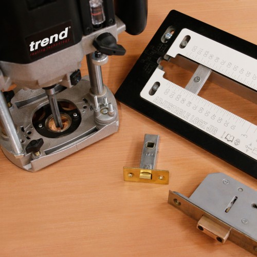

Fitting locks can be a time-consuming job and with some of the high priced doors available it needs care to ensure the fit of the lock case as well as the face plate are uniform and fit squarely and true to the face for perfect operation.
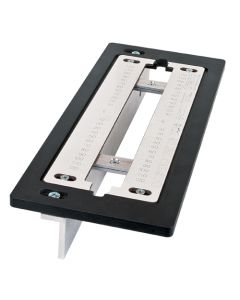
A lock jig will not only speed up the task but also ensure consistency, whether as a one off or on a run of doors. The Trend LOCK/JIG/B also known as the 'Trade' jig will cover an entire range of locks without the need for a set of faceplate and case inserts.
The Setup & Process
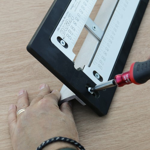

The LOCK/JIG/B is fully adjustable for both the length and width of the lock case as well as the face plate so it can be adjusted for not only common locks but more obscure ones.
Set up is simple to achieve; the long aluminium clamping angle bar on the underside of the jig has two positions to cover doors from 30mm to 80mm thick while retaining a central position on the door edge.


You can also measure the thickness of the door and slide the clamping bar along to a series of metric incremental scribe lines on the underside of the jig. As well as the metric increments, there are a series of scribe positions indicating common door thicknesses for fast setting of the centre position.
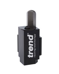
The lock case and faceplate thickness are set with a pair of stepped setting blocks with four incremental steps available, each step covering two common lock case thicknesses of 16mm and 19mm and common faceplate widths of 22.5mm and 25.4mm.
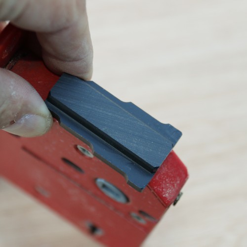

You can use the blocks as quick gauges to check the lock case thickness.
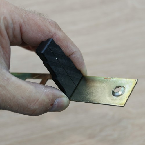

The block can also be used to check the faceplate width.
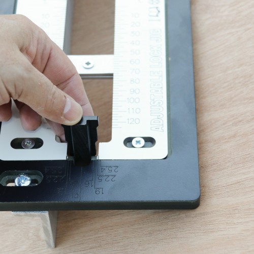

Positioning the blocks into the slots on the jig allows the inset white sliding inserts to move in and set the opening for each position against the setting blocks.
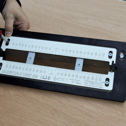

Tighten off the plates to ensure the mortice remains central once routed.
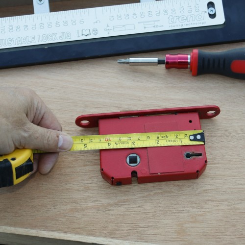

Measure the lock case and allow an additional 10mm overall, to account for the radius ends of the mortice once routed. This prevents the lock case from being too tight for length.
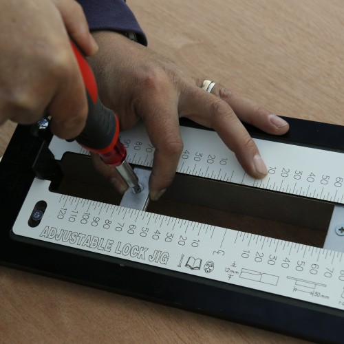

Slide the stops up to the correct position and tighten off. The scale on the insert allows for the guide bush and cutter ratio so the length stops are simply positioned to the correct mark and secured.
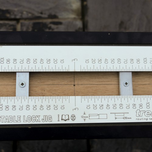

Determine the position on the door for the lock ensuring that it aligns with the lock block on a hollow door and doesn't remove a structural tenon on a rail on a solid door. Mark the centre lines as reference then secure the jig to the door with a couple of clamps.
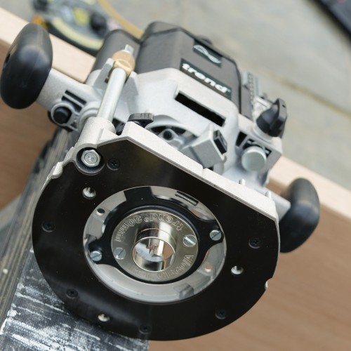

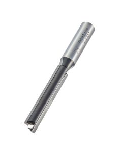
Fit a 30mm guide bush and 12mm diameter cutter TR37X1/2TC to the router.
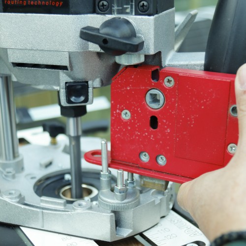

Position the router onto the jig, plunging until the cutter touches the surface of the door. Adjust the turret stop to the depth of the lock allowing an extra few millimetres of extra depth as clearance to ensure the lock case doesn't foul on the bottom of the mortice.
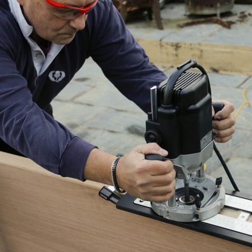

Make a series of plunge cuts to remove the bulk of the waste.
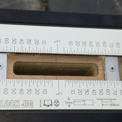

Then run the router along to clean out the slot in a series of passes to ensure the router and cutter aren't overly strained.
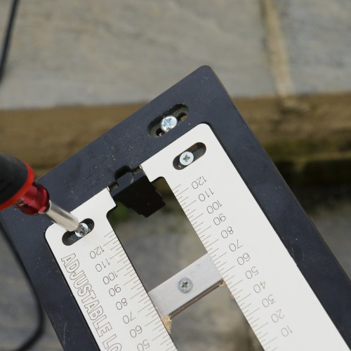

Remove the jig from the door and adjust the insert plates to the correct width to suit the faceplate width using the setting block if it matches the lock being fitted.
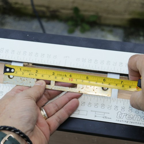

Measure the faceplate length of the lock accurately and halve the measurement.
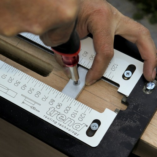

Move the stops up to the corresponding position on the inserts and tightened off, then reposition back on the door to the centrelines.
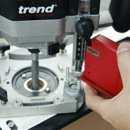

Place the router on the jig and plunge the cutter to the surface of the door and then set the turret stop to the faceplate thickness.
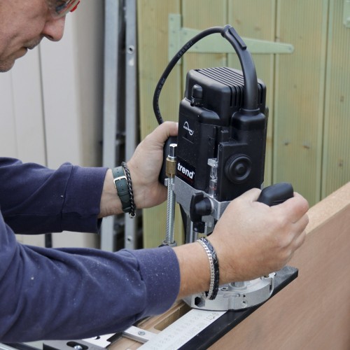

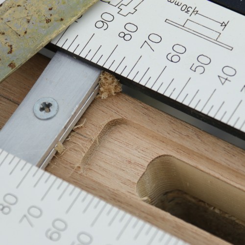

The corners will be rounded from the router cutter.


Square up the corners with a corner chisel C/CHISEL.
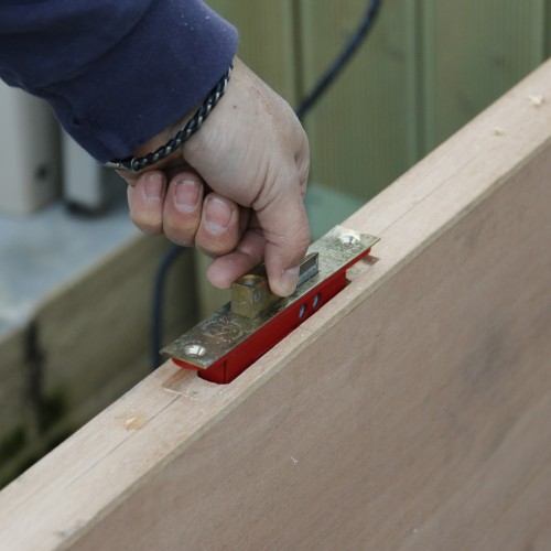

Check the fit of the lock in the case. To ensure you can remove it easily, shoot the bolt to its locked position first so that you have something to pull on to remove it.
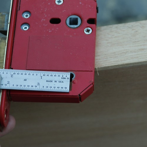

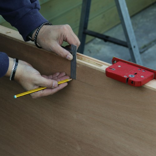

Mark and transfer the position of the keyhole and spindle bar to the door.
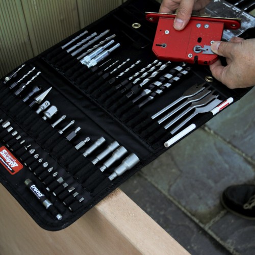

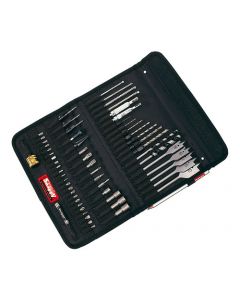
Select suitable drills bits for the spindle and keyhole. The Trend Snappy SNAP/TH2/SET 60-piece has a complete range of drills and screwdriver bits ideal for door hanging and other work.
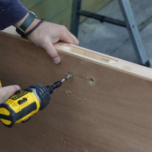

Drill the holes through for the spindle and keyhole and clear out any residual debris in the mortice.
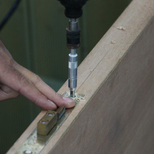

Slide the lock in and secure, drilling the pilots with a hinge self-centring drill bit guide.
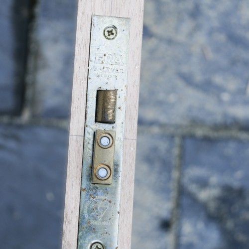

The resulting finish will leave the faceplate let in cleanly and flush to the door edge.

